How to use SPI with the stack ??
-
Hi guys,
today I spent some time getting my MCP3204 working. It´s a 4 channel ADC with an SPI Bus.
I connected the MCP like this:#define SPI1_CLK 18 // D -> Clk -> Pin 11 #define SPI1_MISO 19 // Q -> D Out -> Pin 10 #define SPI1_MOSI 23 // -> D In -> Pin 9 #define SPI1_SS 16 // -> CS -> Pin 8It´s working as expected as far as I don´t use any display stuff from the M5 Stack.
As soon as I ad the following to my code:
 M5.begin(); // true, false, false);
 M5.Lcd.printf("TEST");
things getting wired. The readings of my MCP3204 are wrong.
I convert the AD values to temperature vales since I use some BBQ sensors. And the results are about 2 degrees wrong when adding the M5 Display.
Example: Reading temp without Display -> ~21° and with display ~23° or sometime ~17°
I can do some addition checks with the plain AD values to get a better understanding.But anyway ... What´s wrong in using the SPI bus for a second device?
Are there any drawbacks i don´t know? Any issues?Maybe someone has some explanation for this topic.
Dominik
-
Hi Guys,
I think I figured out the main problem.It has nothing todo with the SPI bus ... It´s the 3,3V line.
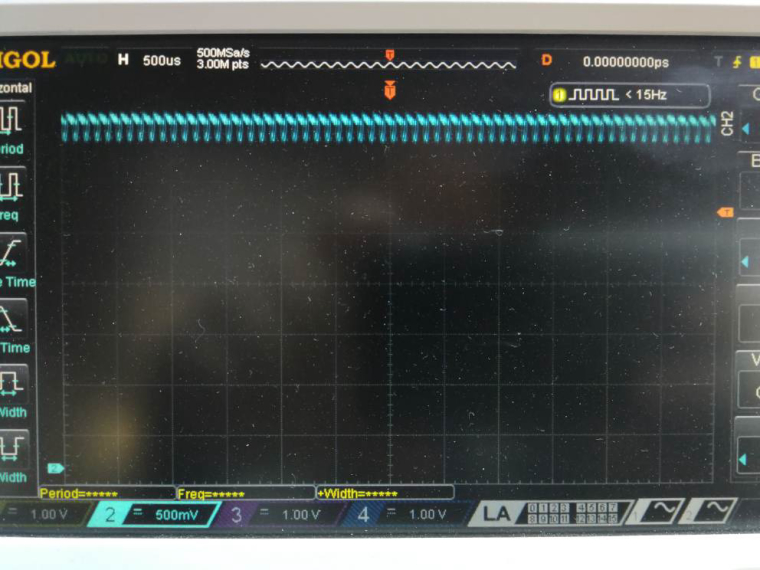
Take a look at the picture. If you set the LCD to 80 (~33%) brightness then the PWM signal is extremly present on the 3,3v line ... And the MCP3204 don´t like that :-)
And this is a picture with 255 (100% on) brightness ...
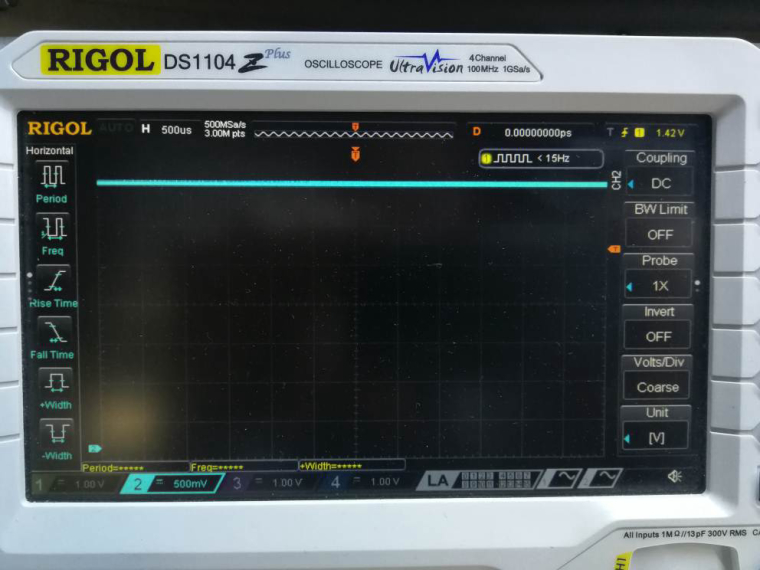
No further explanation needed ...
Dominik
-
Thanks, it's useful.
-
@moelski Have you tried adding a small capacitor to ground?
-
Hi Rob.
Yes there are 100nF directly at the Power supply of the Mcp3204.
But that won't help. I Ordered some lm4040 to have a clean voltage reference.
I think that will help.Regards
Dominik
Hello! It looks like you're interested in this conversation, but you don't have an account yet.
Getting fed up of having to scroll through the same posts each visit? When you register for an account, you'll always come back to exactly where you were before, and choose to be notified of new replies (either via email, or push notification). You'll also be able to save bookmarks and upvote posts to show your appreciation to other community members.
With your input, this post could be even better 💗
Register Login