"Bottom" IO expander pinout
-
Hello everybody !
I've ordered M5Stack Basic kit and I'm preparing my project.
I'm not able to find any schematic / picture that describes the link between MBus to IO of the Bottom module
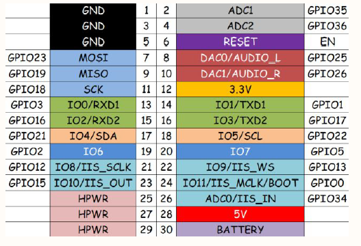
Following Schematic:
MBus have 30 pins with 20 GPIO
Following Bottom module picture:
Bottom module come with 46 pins with 30 IO...
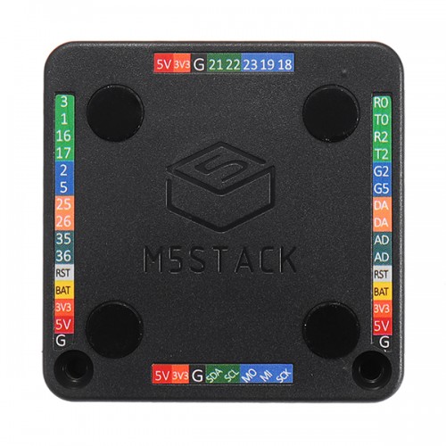
I can figure out connection for 5V, 3V3, GND, RST, BAT but for the other ???
2 pins are named "DA". What does it mean ?
"R0"/"T0": RX/TX from UART 1 ?
"R2"/"T2": RX/TX from UART 2 ?
"2" means GPIO2 ? So what "G2" means ?Anyone can help ? Do you have a document regarding that ?
Many thanks for your help,
Max -
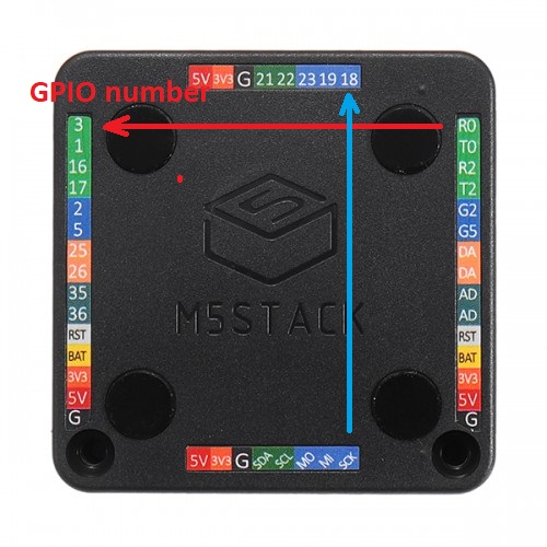
Names on the right side correspond to the GPIO numbers on the left and are connected together.
higher DA mean GPIO25
lower DA mean GPIO26R0/T0 = GPIO3/GPIO1 -> uart0
R2/T2 = GPIO16/GPIO17 -> uart2Similarly, bottom names applies to the gpio numbers at the top.
-
Thanks you so much for your reply !
So, right now I'm understanding that I will have half IO than expected...Thanks again, It helps me a lot
See you
Hello! It looks like you're interested in this conversation, but you don't have an account yet.
Getting fed up of having to scroll through the same posts each visit? When you register for an account, you'll always come back to exactly where you were before, and choose to be notified of new replies (either via email, or push notification). You'll also be able to save bookmarks and upvote posts to show your appreciation to other community members.
With your input, this post could be even better 💗
Register Login