🤖Have you ever tried Chat.M5Stack.com before asking??😎
    M5Stack Community
    • Categories
    • Recent
    • Tags
    • Popular
    • Users
    • Groups
    • Search
    • Register
    • Login

    M5StickC : how to switch 5V out off?

    Scheduled Pinned Locked Moved M5 Stick/StickC
    13 Posts 3 Posters 7.5k Views 2 Watching
    Loading More Posts
    • Oldest to Newest
    • Newest to Oldest
    • Most Votes
    Reply
    • Reply as topic
    Log in to reply
    This topic has been deleted. Only users with topic management privileges can see it.
    • KabronK Offline
      Kabron @felmue
      last edited by Kabron

      This post is deleted!
      1 Reply Last reply Reply Quote 0
      • KabronK Offline
        Kabron
        last edited by

        I tested it - does not work at all

        1 Reply Last reply Reply Quote 0
        • KabronK Offline
          Kabron @felmue
          last edited by Kabron

          @felmue It only switched 5V to Vbatt
          I see the only way to reconnect EXT_BOOST_EN of the BOOST converter to VESP_3V3.

          felmueF 1 Reply Last reply Reply Quote 0
          • felmueF Offline
            felmue @Kabron
            last edited by felmue

            Hello @Kabron

            hmm, I've tested with an M5StickC (not Plus, not Plus2) powered by USB-C (or battery) and an LED attached to the Groove port.

            I agree, EXT_BOOST_EN needs to be turned on, which is exactly what the function I pointed out does. It sets bit 2 of register 0x10 of the AXP. See here. And here - page 34.

            Edit: I just remembered, I think there was a similar discussion a couple of years ago. EXTEN actually seems to exist in two places. Bit 2 in register 0x10 and bit 6 in register 0x12.

            Maybe try to manipulate bit 6 in register 0x12 to see if that works for you?

            Thanks
            Felix

            GPIO translation table M5Stack / M5Core2
            Information about various M5Stack products.
            Code examples

            KabronK 1 Reply Last reply Reply Quote 0
            • KabronK Offline
              Kabron @felmue
              last edited by Kabron

              @felmue I tested it:
              void AXP192::SetPeripherialsPower(uint8_t state) {
              if (!state){
              Write1Byte(0x10, Read8bit(0x10) & 0XFB);
              Write1Byte(0x12, Read8bit(0x12) & 0XBF);
              }
              else if (state) {
              Write1Byte(0x10, Read8bit(0x10) | 0X04);
              Write1Byte(0x12, Read8bit(0x12) | 0X40);
              }

              EXT_BOOST_EN controlled correctly, DC-Boost stops generating, but bypassed input Vbatt to 5V output.

              What an idiot designed this part of schematic?

              I could not identify DC-Boost IC(Sot-23-5 marked IB3KB)/

              1 Reply Last reply Reply Quote 0
              • KabronK Offline
                Kabron
                last edited by

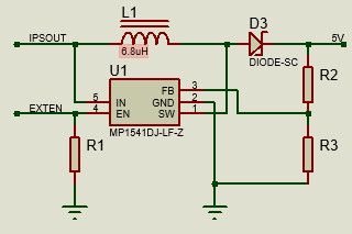
                So, according to schematic switching off 5V is fundamentally impossible. IPSOUT via L1 and D3 allways present at output.

                DCBoost.jpg

                felmueF 1 Reply Last reply Reply Quote 0
                • felmueF Offline
                  felmue @Kabron
                  last edited by

                  Hello @Kabron

                  I start to think that maybe the DC/DC IC has been changed over time in the M5StickC. The DC/DC IC in mine is marked SCAJF and the externally connected components look suspiciously like the 5VOUT_BOOST in the M5StickCPlus schematic.

                  This would at least explain the different results regarding on/off capability.

                  Thanks
                  Felix

                  GPIO translation table M5Stack / M5Core2
                  Information about various M5Stack products.
                  Code examples

                  1 Reply Last reply Reply Quote 0
                  • KabronK Offline
                    Kabron
                    last edited by

                    Definitelly, M5SticC and M5SticC Plus have different schematics. DC-Boost in M5SticC Plus is sgm6603-5.

                    felmueF 1 Reply Last reply Reply Quote 0
                    • felmueF Offline
                      felmue @Kabron
                      last edited by

                      Hello @Kabron

                      I beg to differ. At least between my M5StickCPlus and M5StickC the DC/DC boost circuit and IC look suspiciously identical.

                      M5StickCPlusVsM5StickC_240617.png

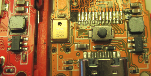
                      on the left: M5StickCPlus; on the right: M5StickC

                      Thanks
                      Felix

                      GPIO translation table M5Stack / M5Core2
                      Information about various M5Stack products.
                      Code examples

                      KabronK 1 Reply Last reply Reply Quote 0
                      • KabronK Offline
                        Kabron @felmue
                        last edited by Kabron

                        @felmue I draw schematic above from my exemplar. Obviously it's too old.
                        IC is SOT-23-5 and its marking corresond with MP1541 datasheet.

                        The root of the evil is M5STACK's absolutely lackadaisical documentation for all the products.

                        1 Reply Last reply Reply Quote 0

                        Hello! It looks like you're interested in this conversation, but you don't have an account yet.

                        Getting fed up of having to scroll through the same posts each visit? When you register for an account, you'll always come back to exactly where you were before, and choose to be notified of new replies (either via email, or push notification). You'll also be able to save bookmarks and upvote posts to show your appreciation to other community members.

                        With your input, this post could be even better 💗

                        Register Login
                        • First post
                          Last post